(이유는 잘 기억이 안나지만) 사용하지 않아서 창고에 몇 년간 놔 둔 PETOI 급식기를 개조해 보았습니다.
참고로, PETOI 급식기는 아래 블로그에 잘 소개되어 있네요.
페토이 자동급식기 추천, PETOI HT P003
페토이 자동급식기 추천, PETOI HT P003 글/사진 ⓒ 2018 땅뽀앤령 오늘은 강아지 자동급식기인, ...
blog.naver.com
오래 전의 제품으로 마이콤이 내장되어 있습니다. 하루에 몇 번을 몇 g을 급식할 것인지 정할 수 있습니다. 다만, 요즘 나오는 신제품과 달리 IoT 기능은 되지 않습니다(같은 회사의 신제품은 IoT가 됩니다).
그래서 PETOI 제품을 분해한 후 모터 및 사료 배출 메커니즘만 이용하기 위해 ESPHome으로 펌웨어(는 아니고 .YAML파일)를 만들고 Odoid XU4에 설치해 둔 Home Assistant에 연결하여 보았습니다.
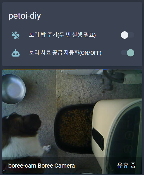
연결 후 Home Assisant의 모습
이 장치 이외에 카메라도 하나 추가하여 현관문을 나가지 않아도 사료가 잘 나왔는지 확인할 수 있게 되었습니다.
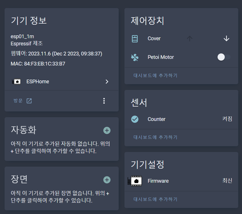
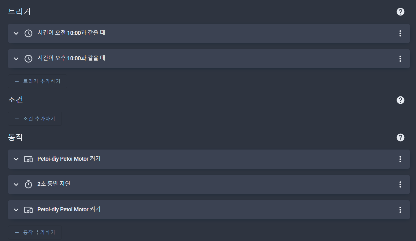
어쨌든 PETOY-DIY 장치가 홈어시스턴트에 연결되면 아래와 같은 기기 정보를 볼 수 있고, "Petoi Motor"를 누르면 작동하게 됩니다. 아래에는 아직 없지만 시각에 따라 자동화를 추가하면 하루에 필요한 시각에 급식을 할 수가 있겠습니다.
Counter는 급식량을 조절하기 위한 것으로써, 버튼식으로 센서가 달려 있어서 급식기 내부 부품이 회전할 때 4방향의 돌기로 인해 버튼이 클릭이 되면 한 바퀴 회전을 인식하는 방식으로 하드웨어가 설계되어 있었습니다.
필요한 부품
1) ESP8266 보드 - GND가 3개라서 편리합니다.
https://ko.aliexpress.com/item/1005004522421255.html
5447.0₩ |Freenova ESP8266 개발 보드 (Arduino IDE 호환), ESP 12S 온보드 Wi Fi, MicroPython C 코드, 상세한 자습
Smarter Shopping, Better Living! Aliexpress.com
ko.aliexpress.com
2) 모터 드라이버 - L298N보다 작아서 좋습니다. EN(motor enable)핀만 없고 사용법은 같았습니다.
https://smartstore.naver.com/makerspace/products/6536880519
아두이노 라즈베리파이 701 듀얼 DC모터 드라이버 : 송파 메이커스페이스
아두이노 라즈베리파이 701 듀얼 DC모터 드라이버
smartstore.naver.com
작업 과정
Home Assistant(이하, HA)를 Supervisor 모드로 설치하고, HA에 HTTPS로 접속하도록 되어 있다면 애드온에서 ESPHome을 설치하여 장치 등록부터 펌웨어(.YAML) 작성 및 테스트를 편리하게 할 수 있습니다. 처음에는 USB(to Serial)를 통해 펌웨어를 올리고 ESP8266보드가 WiFi에 접속되면 Wireless로 펌웨어를 올리고 테스트하는 것이 상당히 편리합니다.
다행히 PETOI 내부의 모터는 5V로도 잘 작동이 되었고, 별다른 문제는 없었으나 회전을 카운트하는 버튼 센서는 처음 접하는 것이라서 약간 시간이 걸렸습니다. 결론은 간단한데요, 버튼식 센서는 릴레이처럼 NC / NO / C로 세개의 커넥터가 있는데 Normal Open과 Common에 결선이 되어 있습니다. Common은 ESP8266의 GND에 연결하고, GPIO12에는 Normal Open핀을 연결합니다. Normal Open 즉 평소에는 연결이 없으므로 GPIO12는 Pullup을 시켜주고 Inverted를 true로 주어서 GND로 떨어질 때 버튼이 눌린 것으로 인식하도록 하면 되었습니다.
ESP8266의 GPIO4와 GPIO14는 PWM으로 모터를 제어하기 위한 포트입니다. 아래 소스를 보면 아주 간단하게 모터가 제어되는 것을 알 수 있습니다. 참고로 ESP32는 모터 제어 방법이 다릅니다(platform: esp8266_pwm 대신 platform: ledc를 이용). 가장 간단한 모터 제어 방법으로 hbridge 플랫폼을 사용하는 fan으로 세팅하였습니다.
또 하나 시간 소비한 것은 버튼 클릭 이벤트 처리 부분입니다. 버튼이 딸깍할 때 한번 이상 누른 것으로 인식이 되는 경우가 있는데, ESPHome에서 추천하는 여러 가지 방식으로는 잘 해결이 안되어서, 그냥 무식하게 버튼 사이에 눌린 시간 간격(2초 초과 6초 미만 사이)일 때만 버튼이 눌린 것으로 인식하도록 코딩 하였습니다.
소스코스
esphome:
  name: petoi-diy
  friendly_name: petoi-diy

esp8266:
  board: esp01_1m

# Enable logging
logger:

# Enable Home Assistant API
api:
  encryption:
    key: ""

ota:
  password: ""

wifi:
  ssid: !secret wifi_ssid
  password: !secret wifi_password

  #manual_ip:
  #  # Set this to the IP of the ESP
  #  static_ip: 192.168.0.137
  #  # Set this to the IP address of the router. Often ends with .1
  #  gateway: 192.168.0.1
  #  # The subnet of the network. 255.255.255.0 works for most home networks.
  #  subnet: 255.255.255.0

  # Enable fallback hotspot (captive portal) in case wifi connection fails
  ap:
    ssid: "Petoi-Diy Fallback Hotspot"
    password: ""

captive_portal:

globals:
- id: prev_timestamp
  type: long
  initial_value: "0"
- id: rotation_count
  type: int
  initial_value: "0"

time:
  - platform: sntp
    id: sntp_time

# Normal Open
binary_sensor:
  - platform: gpio
    pin:
      number: GPIO12
      inverted: true
      mode:
        input: true
        pullup: true
    name: "Counter"
    on_press:
      then:
        - lambda: |-
            auto time = id(sntp_time).now();
            long now_timestamp = time.timestamp;


            if(now_timestamp > (id(prev_timestamp) + 2) && now_timestamp < (id(prev_timestamp) + 7)) {
              ESP_LOGD("petoi-diy", "on_press valid : now_timestamp = %ld", now_timestamp);
              id(rotation_count) += 1;
              // timeout, 1, 2, 3
              if(id(rotation_count) > 2) {
                auto call2 = id(my_motor).turn_off();
                call2.perform();
                id(rotation_count) = 0;
              }
            }

            if(now_timestamp >= (id(prev_timestamp) + 7)) {
              id(rotation_count) = 0;
              ESP_LOGD("petoi-diy", "timeout : now_timestamp = %ld", now_timestamp);
            }

            id(prev_timestamp) = now_timestamp;

output:
  - platform: esp8266_pwm
    id: motor_forward_pin
    pin: GPIO4
  - platform: esp8266_pwm
    id: motor_reverse_pin
    pin: GPIO14

fan:
  - platform: hbridge
    id: my_motor
    name: "Petoi Motor"
    pin_a: motor_forward_pin
    pin_b: motor_reverse_pin
    decay_mode: slow   # slow decay mode (braking) or fast decay (coasting).

cover:
  - platform: template
    name: "Cover"
    id: my_cover
    open_action:
      - lambda: |-
          auto call1 = id(my_motor).turn_on();
          id(my_motor).direction = FanDirection::FORWARD;
          call1.perform();
작동 로그
처음에 모터를 작동하면 prev_timestamp값이 현재 시각과 멀기 때문에 timeout이 먼저 나옵니다. 그 후 3번 on_press 이벤트를 감지하면 모터를 멈추는 방법으로 하면 잘 작동이 되었습니다.
[13:19:16][D][fan:021]: 'Petoi Motor' - Setting:
[13:19:16][D][fan:024]:   State: ON
[13:19:16][D][fan.hbridge:012]: Setting speed: a: 0.00, b: 1.00
[13:19:16][D][fan:092]: 'Petoi Motor' - Sending state:
[13:19:16][D][fan:093]:   State: ON
[13:19:16][D][fan:095]:   Speed: 100
[13:19:16][D][fan:101]:   Direction: FORWARD
[13:19:16][D][binary_sensor:036]: 'Counter': Sending state OFF
[13:19:21][D][binary_sensor:036]: 'Counter': Sending state ON
[13:19:21][D][petoi-diy:080]: timeout : now_timestamp = 5938
[13:19:21][D][binary_sensor:036]: 'Counter': Sending state OFF
[13:19:26][D][binary_sensor:036]: 'Counter': Sending state ON
[13:19:26][D][petoi-diy:068]: on_press valid : now_timestamp = 5943
[13:19:26][D][binary_sensor:036]: 'Counter': Sending state OFF
[13:19:31][D][binary_sensor:036]: 'Counter': Sending state ON
[13:19:31][D][petoi-diy:068]: on_press valid : now_timestamp = 5948
[13:19:31][D][binary_sensor:036]: 'Counter': Sending state OFF
[13:19:35][D][binary_sensor:036]: 'Counter': Sending state ON
[13:19:35][D][petoi-diy:068]: on_press valid : now_timestamp = 5953
[13:19:35][D][fan:021]: 'Petoi Motor' - Setting:
[13:19:35][D][fan:024]:   State: OFF
[13:19:35][D][fan.hbridge:012]: Setting speed: a: 0.00, b: 0.00
[13:19:35][D][fan:092]: 'Petoi Motor' - Sending state:
[13:19:35][D][fan:093]:   State: OFF
[13:19:35][D][fan:095]:   Speed: 100
[13:19:35][D][fan:101]:   Direction: FORWARD
전원
소비전력을 측정해 보니까 모터가 작동하는 동안 130mA@5V가량 소비가 되었습니다. 일반적인 USB 전원을 꼽아주어도 잘 된다는 뜻입니다. DC잭으로 USB전원이 들어갈 수 있도록 기존 USB 케이블을 개조하여 마침 CCTV때문에 나와 있는 USB포트가 있어서 상시 전원으로 연결해 주었습니다.
'DIY' 카테고리의 다른 글
| ASUS 공유기 방열팬 부착 후 CPU온도 85도에서 69도로 하강 (0) | 2023.10.20 |
|---|---|
| 근접 자동 열림 급식기 - auto pet feeder, ESPHome, Home Assistant, DIY (2) | 2023.10.11 |
| 트레일블레이저 블랙박스 자가 설치 blackbox DIY (0) | 2023.09.19 |
| 자전거 후방 감지기 DIY - LD2410 센서 이용 (1) | 2023.06.16 |
| 잠자던 소니 MDR-1AM2 헤드폰을 무선으로 개조 (0) | 2023.04.27 |


